How to Set Up a Brand New Cisco Layer 3 Switch
It is a familiar Monday-morning ticket: users in Finance can reach their own file share but nothing in Engineering. The printers in VLAN 30 answer pings from the IT subnet but not from the floor they actually sit on. Every device can reach its local gateway — and nothing beyond it. The Layer 2 switching is working exactly as designed; what the network is missing is something to route between those VLANs. That is the job of a Cisco Layer 3 switch, and getting one from sealed box to production-ready is what this guide covers.
In a modern enterprise network, inter-VLAN routing is not an edge case — it is most of the traffic. Segmentation by department, function, and security zone means almost every meaningful flow crosses a VLAN boundary: workstation to server, phone to call manager, badge reader to security appliance. Pushing all of that through a router-on-a-stick or, worse, a firewall that was never sized for east-west traffic creates a bottleneck the business feels every day. A correctly configured Layer 3 switch routes that traffic in hardware at wire speed — and a misconfigured one produces exactly the Monday-morning ticket above.
A practical setup procedure for Cisco Catalyst 9000-series Layer 3 switches running IOS-XE — focused on the C9300 and C9500. Covers the day-zero steps that most setup guides skip: Plug-and-Play disable, Smart Licensing registration, management VRF isolation, SVI routing, HSRP gateway redundancy, access-port hardening, and stack configuration.
Audience: network engineers and IT directors deploying or refreshing Catalyst 9000 infrastructure in enterprise campus environments. Assumes familiarity with IOS-XE CLI, VLAN concepts, and basic routing.
The 5-minute version
Ten steps from sealed box to routing production traffic. Each links to the full procedure below.
- Disable PnP (unless Catalyst Center manages it)
- Hostname, NTP, scrypt admin user
- Register Smart Licensing — day one
- OOB management on Gi0/0 + SSH with ACL
- Enable ip routing, build VLANs and SVIs
- Trunks with explicit allowed-VLAN lists
- Static default or OSPF with BFD
- HSRP gateway pair, hosts on the virtual IP
- Harden: snooping, DAI, SNMPv3, syslog
- Verify with the six commands, back up config
Take it to the data center: the complete day-zero procedure as a printable 2-page checklist — every phase, every checkbox, no scrolling.
What is a Layer 3 switch?
A Layer 3 switch is a network switch that forwards traffic by MAC address within a VLAN (Layer 2) and routes traffic by IP address between VLANs (Layer 3), performing both functions in dedicated switching hardware rather than a general-purpose CPU. Cisco documentation often calls the same device a multilayer switch; on the Catalyst 9000 family, Layer 3 capability is native to the platform.
The distinction that matters operationally is where the forwarding decision happens. A traditional router receives a packet, interrupts a CPU, performs a route lookup in software or a software-assisted path, rewrites the header, and forwards. A Catalyst Layer 3 switch programs its routing table, ARP adjacencies, and ACLs into a forwarding ASIC (the UADP chip on the Catalyst 9000 family) via OSI Layer 2/Layer 3 lookup tables built by Cisco Express Forwarding (CEF). Once programmed, the ASIC routes packets at line rate with the CPU uninvolved — the same five-stage hardware path shown in Figure 03 later in this guide. That is why a 1U Catalyst 9300 can route hundreds of gigabits of inter-VLAN traffic while a software router at the same price point saturates in the low single digits.
The trade-off: a Layer 3 switch is optimized for high-density Ethernet and fast simple forwarding. It is not the right tool for WAN terminations, large-scale NAT, full Internet BGP tables, or per-flow services like stateful inspection — that remains router and firewall territory.
| Feature | Layer 2 switch | Layer 3 switch | Router |
|---|---|---|---|
| Forwarding decision | MAC address table | MAC table + hardware IP routing (CEF/ASIC) | IP routing table (software or hardware-assisted) |
| Inter-VLAN routing | No — requires external device | Yes — native, wire-speed via SVIs | Yes — via subinterfaces (router-on-a-stick) |
| Routing protocols | None | Static, OSPF, EIGRP, BGP (license-dependent) | Full suite, large table capacity |
| Throughput profile | Line rate L2 | Line rate L2 + L3 (ASIC) | Platform-bound; far lower per dollar |
| Latency | Microseconds | Microseconds | Tens of microseconds to milliseconds |
| NAT / stateful services | No | Limited or none | Yes |
| WAN interfaces | No | No (Ethernet only) | Yes (fiber handoffs, LTE, legacy circuits) |
| Port density | High | High (24-48 ports + uplinks per RU) | Low |
| Typical placement | Access layer | Access, distribution, campus core | WAN edge, Internet edge, branch perimeter |
When to use a Layer 3 switch
Deploy a Layer 3 switch wherever routed traffic stays on Ethernet and stays inside your administrative domain:
- Campus networks — the canonical case. SVIs on the distribution or collapsed-core switch act as the default gateway for every user VLAN; traffic between departments never touches a router.
- Enterprise branch offices — a single Catalyst 9300 can be the access switching, the inter-VLAN router, and the LAN side of the WAN handoff, with one static default route toward the branch router or SD-WAN appliance.
- Data centers — top-of-rack and end-of-row L3 switching keeps server-to-server (east-west) traffic in hardware. At scale this becomes spine-leaf on Nexus, a different platform with a different procedure, but the principle is identical.
- Distribution-layer deployments — aggregating dozens of access closets with routed uplinks toward the core, summarizing routes outward, and terminating user gateways with HSRP pairs.
- Any inter-VLAN routing scenario where a router-on-a-stick design has become the bottleneck — one trunk into one router interface caps the entire inter-VLAN aggregate at that single link.
Reach for a router instead when the requirement is a WAN or Internet termination, large-scale NAT/PAT, full BGP Internet tables, per-tunnel encryption at scale, or advanced QoS shaping on slow circuits. In practice every campus needs both: Layer 3 switches for the interior, routers (or SD-WAN appliances) at the edge. If the estate has accumulated a mix of both with unclear roles, that is an architecture conversation — WUC professional services runs exactly that assessment.
Planning a Catalyst deployment or refresh? Tell our engineers what is in your estate — model selection, licensing, and post-SMARTnet options scoped in writing, without leaving this page.
Reference topology: three VLANs behind one Layer 3 switch
Every configuration step in this guide maps onto the topology below: three VLANs — users, servers, and voice — terminating on a Catalyst Layer 3 switch, with a routed uplink to the Internet edge router.
Reference topology · inter-VLAN routing with an upstream router
Packet flow, concretely: a workstation at 10.10.10.50 opens a session to a server at 10.10.20.80. The workstation compares destination to its own subnet, sees a mismatch, and forwards the frame to its default gateway — the SVI at 10.10.10.1. The switch strips the VLAN 10 encapsulation, performs a hardware route lookup, finds 10.10.20.0/24 directly connected on SVI 20, rewrites the destination MAC to the server (resolving via ARP if needed), and forwards out the server port tagged VLAN 20. Round trip, the path never leaves the switch. Only flows with no more-specific route — Internet traffic — follow the default route up the /30 to the edge router. Keep this picture in mind during configuration: every vlan, interface Vlan, and ip route command below builds one piece of it.
Which Catalyst model are you actually deploying?
Cisco’s enterprise L3 switch lineup splits into four roles. Picking the right model is the first decision and the one that’s hardest to undo.
| Model family | Role | Typical use | L3 throughput | Stacking | Common license tier |
|---|---|---|---|---|---|
| Catalyst 9200 / 9200L | Access with limited L3 | Branch, small campus access | Up to 80 Gbps | StackWise-160 / 80 (8 units) | Network Essentials |
| Catalyst 9300 / 9300X | Stackable access / small distribution | Most common enterprise L3 access | 400-1000 Gbps | StackWise-480 / 1T (8 units) | Essentials or Advantage |
| Catalyst 9400 | Modular chassis | Aggregation, dense access | Up to 9 Tbps | Chassis (redundant supervisors) | Advantage |
| Catalyst 9500 | Fixed core / aggregation | Distribution / core | Up to 4 Tbps | StackWise Virtual (2 units) | Advantage |
| Catalyst 9600 | Modular core | Campus core / very large distribution | Up to 25.6 Tbps | Chassis / StackWise Virtual | Advantage |
| Nexus 9300 / 9500 | Data center fabric | DC top-of-rack, spine-leaf | NX-OS — different procedure | vPC (not StackWise) | NX-OS licensing |
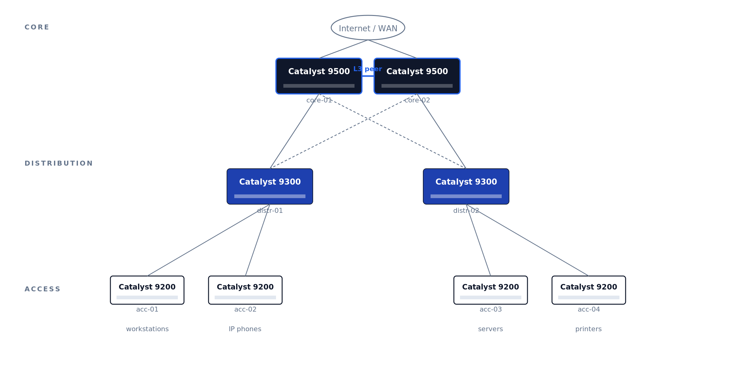
A typical three-tier campus uses the 9200 at access, 9300 at distribution, and 9500 at the core (Figure 01).
Figure 01 · Three-tier campus topology
Legacy 3850, 3650, and 4500-X are still in production but hit End-of-Software-Support in 2025-2026 — new deployments should default to C9000.
The Catalyst estates we take over for maintenance rarely fail on hardware — they fail on records. The recurring pattern: mixed 3850-and-9300 closets mid-migration with no cutover plan, stack rings cabled but never verified (one member silently running a different IOS-XE train), and license tiers that do not match what the config actually uses — discovered only when the renewal quote arrives. An hour spent on Phase 0 decisions and documentation saves a forensic week at refresh time.
Before unboxing — decisions to lock down
Five questions, all answered on paper before the switch leaves the box:
1. What’s the role and physical location? Top-of-rack? Distribution? Campus core? The role determines uplink architecture (LACP to two upstream cores? StackWise Virtual pair?) and whether you need to peer with anything via OSPF/BGP.
2. What’s the management plan? Out-of-band management network is the right answer for any production Catalyst. The C9300 has a dedicated GigabitEthernet0/0 management port physically isolated from the data-plane ports — use it. In-band management on the SVI works but loses you access the moment you fat-finger an ACL.
3. What’s the IP plan? Management IP, every SVI subnet, every routed port, every BGP/OSPF peer. Document in NetBox, phpIPAM, or whatever your IPAM of record is. Spreadsheets get stale.
4. What software version? Cisco publishes a Suggested Release per platform on the release-tracking page. As of the November 2025 update to that page, Cisco lists IOS-XE 17.12.6 and 17.15.4 as the recommended C9300 releases — prefer the Extended-Maintenance trains (17.12.x and 17.15.x) over Standard-Support releases, and migrate off 17.3.x, which has an announced end-of-life.
5. Are you using Cisco DNA Center / Catalyst Center? If yes, the switch can self-onboard via Plug and Play. If no, you’ll be doing this by hand — and you’ll want to disable PnP before the first boot.
Physical setup and first power-on
Rack, ground (rack ground bonding to the chassis ground lug, not just the chassis screw), cable: dual PSUs to dual circuits, console cable to your laptop, uplinks unplugged for now. Console settings: 9600 8N1, no flow control. The C9300X and newer C9500 ship with both RJ-45 serial and USB-C console — same settings, different device path.
The C9300 boot sequence: ROMMON loader (~10s) → IOS-XE bootloader (~30s) → Linux kernel and IOSd (~90s) → “Press RETURN to get started” — but if PnP is enabled (the default), it will attempt DHCP and DNS-based PnP discovery for 5-10 minutes before giving up. Press RETURN to skip.
Factory-reset a refurb/return-from-stock unit before anything else:
Switch# write erase
Switch# delete /force flash:vlan.dat
Switch# factory-reset all secure 1-pass
Switch# reload
Disable PnP if you’re not using Catalyst Center
First command on a non-DNA-managed switch. Skip it and every reboot hangs 10 min on PnP discovery.
Disable the zero-touch profile and the startup-VLAN trigger
Switch# configure terminal
Switch(config)# pnp profile pnp-zero-touch
Switch(config-pnp-init)# no transport http
Switch(config-pnp-init)# exit
Switch(config)# no pnp startup-vlan
Switch(config)# end
Switch# write memory
On newer code (IOS-XE 17.6+): pnpa service discovery stop from privileged-exec mode achieves the same in one command.
Set hostname, time, admin user
Hostname, NTP, domain
Switch(config)# hostname dc1-distr-c9300-01
dc1-distr-c9300-01(config)# clock timezone EST -5 0
dc1-distr-c9300-01(config)# ntp server 10.0.0.10 prefer
dc1-distr-c9300-01(config)# ntp server 10.0.0.11
dc1-distr-c9300-01(config)# ntp source GigabitEthernet0/0
dc1-distr-c9300-01(config)# ip domain name corp.example.com
Strong admin user, disable defaults
dc1-distr-c9300-01(config)# username netadmin privilege 15 algorithm-type scrypt secret <STRONG_PASSWORD>
dc1-distr-c9300-01(config)# no username admin
dc1-distr-c9300-01(config)# no username cisco
dc1-distr-c9300-01(config)# enable algorithm-type scrypt secret <STRONG_ENABLE_PASSWORD>
dc1-distr-c9300-01(config)# service password-encryption
Scrypt (secret 9) is the strongest password hash IOS-XE supports. Default admin and cisco accounts ship enabled on some refurb units — always disable.
Smart Licensing — the step that breaks most fresh deployments
IOS-XE 16.10+ requires Smart Licensing. IOS-XE 17.3.2+ uses Smart Licensing Using Policy (SLUP). Both grant a 90-day eval period. After 90 days without registration: feature throttling, persistent CLI warnings, logged enforcement events that auditors will ask about.
Register during initial deployment, not after the 90-day timer expires. Re-registration after enforcement triggers requires Cisco TAC intervention on some platforms. The CSSM token install is a 30-second step; the recovery if you miss the window is hours.
Unregistered Smart Licensing is the single most common finding when we baseline an inherited Catalyst estate. The switch works fine for 90 days, the project team moves on, and the eval timer expires in production — usually noticed when an auditor asks about the enforcement events in the logs, or when a TAC case for an unrelated issue stalls on entitlement. Registration is a 30-second step during deployment and an hours-long recovery after enforcement.
Three deployment paths: direct CSSM (internet-connected), on-prem SSM (your local appliance syncs to Cisco), or air-gapped reservation (SLR/PLR — manual code exchange).
dc1-distr-c9300-01(config)# license smart transport smart
dc1-distr-c9300-01(config)# license smart url default
dc1-distr-c9300-01# license smart trust idtoken <TOKEN_FROM_CSSM> all
Verify with show license summary, show license status, show license usage. Status should read REGISTERED and AUTHORIZED — not EVAL.
Configure management VLAN and SSH
Use the dedicated management interface (GigabitEthernet0/0) for OOB. It’s in a separate VRF (Mgmt-vrf) by default and isolated from the data plane.
dc1-distr-c9300-01(config)# interface GigabitEthernet0/0
dc1-distr-c9300-01(config-if)# description OOB-MGMT
dc1-distr-c9300-01(config-if)# vrf forwarding Mgmt-vrf
dc1-distr-c9300-01(config-if)# ip address 10.99.99.10 255.255.255.0
dc1-distr-c9300-01(config-if)# no shutdown
dc1-distr-c9300-01(config)# ip route vrf Mgmt-vrf 0.0.0.0 0.0.0.0 10.99.99.1
dc1-distr-c9300-01(config)# ip ssh version 2
dc1-distr-c9300-01(config)# crypto key generate rsa modulus 2048 label SSH-KEY
dc1-distr-c9300-01(config)# line vty 0 15
dc1-distr-c9300-01(config-line)# transport input ssh
dc1-distr-c9300-01(config-line)# login local
dc1-distr-c9300-01(config-line)# access-class MGMT-ACL in vrf-also
dc1-distr-c9300-01(config)# ip access-list standard MGMT-ACL
dc1-distr-c9300-01(config-std-nacl)# permit 10.0.0.0 0.255.255.255
dc1-distr-c9300-01(config-std-nacl)# deny any log
vrf forwarding Mgmt-vrf isolates management traffic from the data plane. crypto key generate rsa with explicit label is required or SSH fails silently. access-class ... vrf-also matches both default and management VRF; without vrf-also, Mgmt-vrf bypasses the ACL entirely.
Configure Layer 3 routing
Enable IP routing globally:
dc1-distr-c9300-01(config)# ip routing
dc1-distr-c9300-01(config)# ipv6 unicast-routing
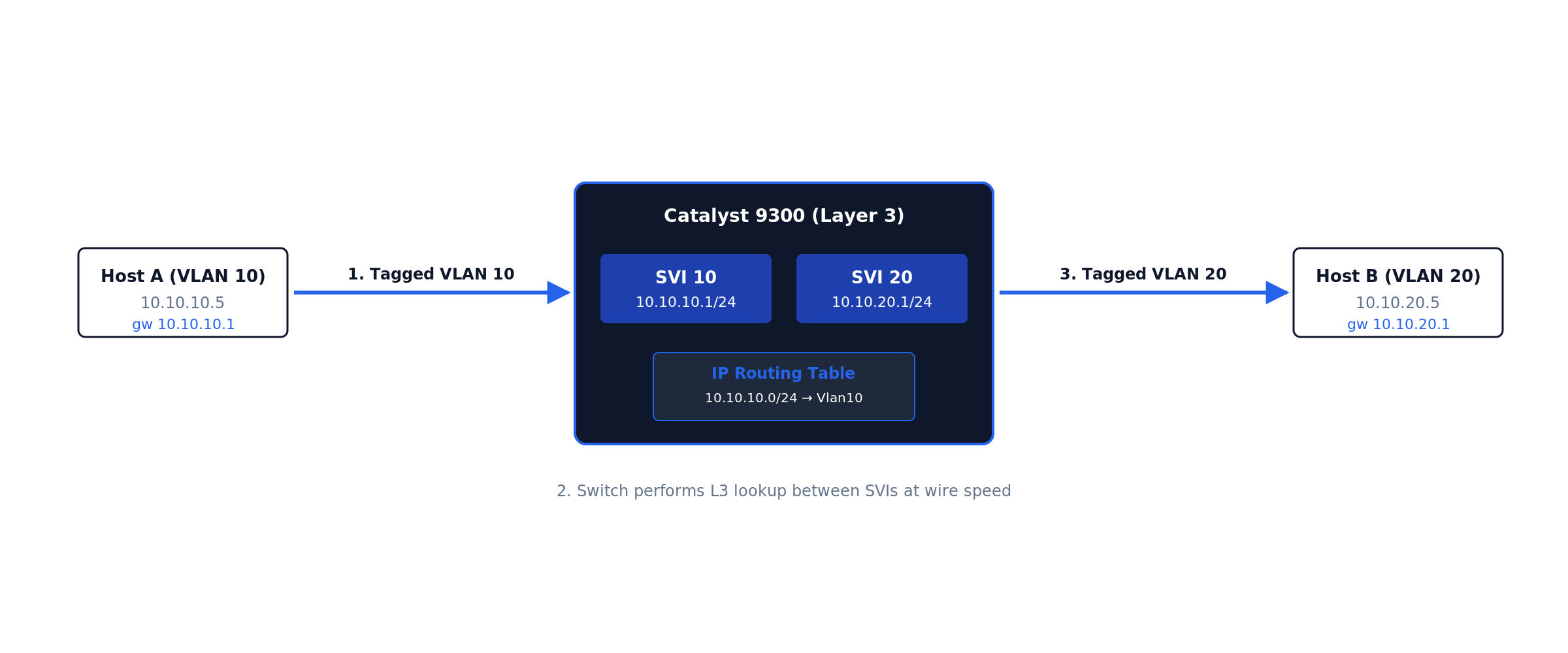
Create VLANs and their SVIs. The SVI is a virtual L3 interface bound to a VLAN — its IP becomes the gateway for hosts in that VLAN (Figure 02 shows the routing flow).
dc1-distr-c9300-01(config)# vlan 10
dc1-distr-c9300-01(config-vlan)# name USERS
dc1-distr-c9300-01(config)# interface Vlan10
dc1-distr-c9300-01(config-if)# ip address 10.10.10.1 255.255.255.0
dc1-distr-c9300-01(config-if)# ip helper-address 10.0.0.50
dc1-distr-c9300-01(config-if)# no shutdown
Figure 02 · SVI inter-VLAN routing flow
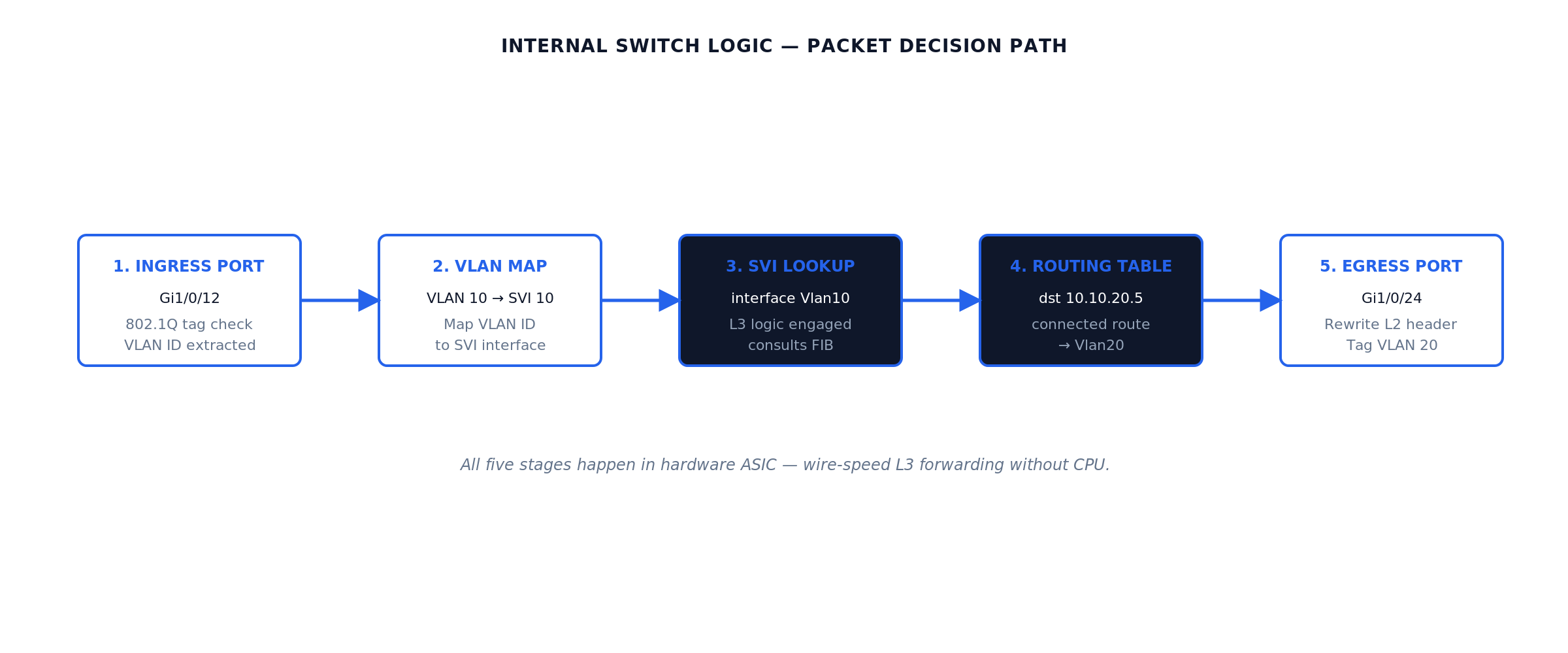
Internally, the switch performs five decision stages in hardware ASIC at wire speed (Figure 03):
Figure 03 · VLAN → SVI → routing-table data path
RFC 1812 defines the host-routing behavior the SVI implements. The L3 switch is a high-speed hardware router with embedded L2 ports.
ip helper-address forwards DHCP broadcasts to your DHCP server — without it, users in the VLAN never receive a DHCP lease. The relay rewrites the broadcast as a unicast packet routed to the configured helper IP (Figure 07 shows the flow).
Repeat for the remaining VLANs in the reference topology. Expected behavior after each no shutdown: the SVI shows up/up in show ip interface brief only once the VLAN exists and at least one physical port in that VLAN is up — an SVI with no live ports stays down by design (autostate). This surprises engineers staging switches on the bench with nothing plugged in.
dc1-distr-c9300-01(config)# vlan 20
dc1-distr-c9300-01(config-vlan)# name SERVERS
dc1-distr-c9300-01(config)# vlan 30
dc1-distr-c9300-01(config-vlan)# name VOICE
dc1-distr-c9300-01(config)# interface Vlan20
dc1-distr-c9300-01(config-if)# ip address 10.10.20.1 255.255.255.0
dc1-distr-c9300-01(config-if)# no shutdown
dc1-distr-c9300-01(config)# interface Vlan30
dc1-distr-c9300-01(config-if)# ip address 10.10.30.1 255.255.255.0
dc1-distr-c9300-01(config-if)# ip helper-address 10.10.20.50
dc1-distr-c9300-01(config-if)# no shutdown
Access ports carrying a phone and a PC use the voice-VLAN construct — one physical port, two VLANs, no trunk configuration on the host side:
dc1-distr-c9300-01(config)# interface GigabitEthernet1/0/12
dc1-distr-c9300-01(config-if)# switchport mode access
dc1-distr-c9300-01(config-if)# switchport access vlan 10
dc1-distr-c9300-01(config-if)# switchport voice vlan 30
dc1-distr-c9300-01(config-if)# spanning-tree portfast
Default route — the step that connects everything else to the world. In the reference topology the switch knows VLANs 10/20/30 because they are directly connected; it knows nothing about the Internet. A small site that does not justify a routing protocol uses one static default toward the edge router, and the edge router needs return routes for the user subnets (or a summary):
dc1-distr-c9300-01(config)# ip route 0.0.0.0 0.0.0.0 10.255.0.1

! verify:
dc1-distr-c9300-01# show ip route static
S*    0.0.0.0/0 [1/0] via 10.255.0.1
Why this matters: the single most common “inter-VLAN routing works but Internet does not” ticket is a missing or wrong default route — covered with the other failure modes in the troubleshooting section. Larger campuses skip the static and learn the default via OSPF from the core, which is the next step.
Choose a routing protocol. OSPF is the most common for new Cisco campus deployments:
dc1-distr-c9300-01(config)# router ospf 1
dc1-distr-c9300-01(config-router)# router-id 10.99.99.10
dc1-distr-c9300-01(config-router)# passive-interface default
dc1-distr-c9300-01(config-router)# no passive-interface TenGigabitEthernet1/1/1
dc1-distr-c9300-01(config-router)# no passive-interface TenGigabitEthernet1/1/2
dc1-distr-c9300-01(config-router)# network 10.0.0.0 0.255.255.255 area 0
dc1-distr-c9300-01(config-router)# auto-cost reference-bandwidth 100000
dc1-distr-c9300-01(config-router)# bfd all-interfaces
Default OSPF hello/dead intervals give 40-second failover. Bidirectional Forwarding Detection (BFD) drops detection to sub-second by sending lightweight 50ms hello packets. Production campus cores should always enable BFD on OSPF interfaces.
OSPF area design on a 9500 core
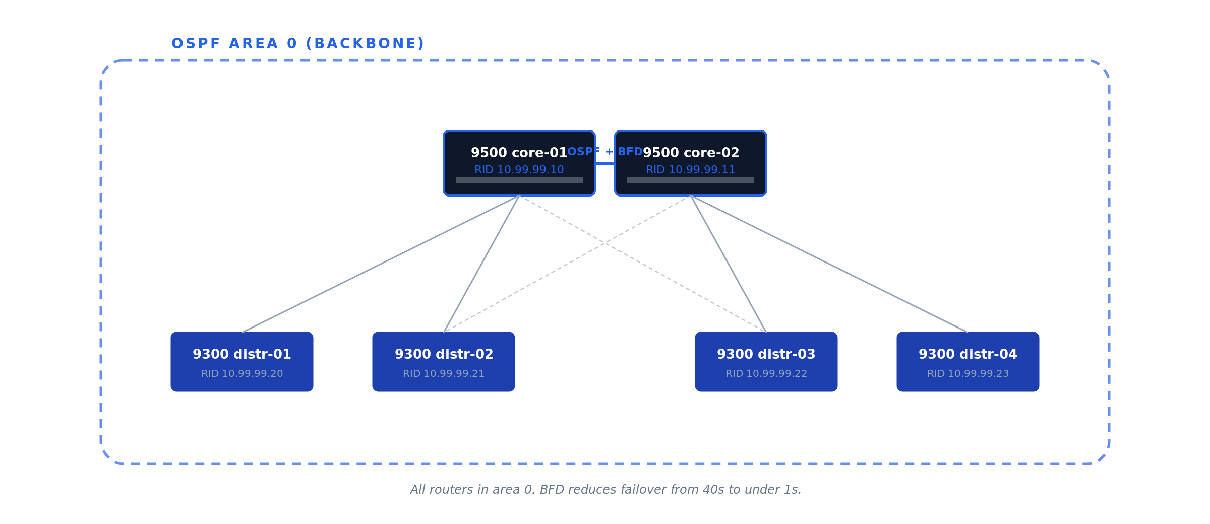
A two-9500 core typically runs all routers in OSPF area 0 (the backbone area), with the distribution switches as additional area 0 members. For larger campuses, distribution switches can run their own areas with the cores as ABRs — but that’s only worth the complexity above ~20 routers per area. Figure 04 shows the simple two-core layout.
Figure 04 · OSPF area 0 design — two cores, four distribution switches
Gateway redundancy with HSRP
A single L3 switch as the default gateway for hundreds of users is a single point of failure. Hot Standby Router Protocol (HSRP, Cisco proprietary) and Virtual Router Redundancy Protocol (VRRP, RFC 5798) both solve this by presenting a virtual IP that two physical switches share (Figure 05).
Use HSRP for all-Cisco environments (simpler config, slightly faster HSRPv2 convergence). Use VRRP for mixed-vendor (standards-based). Functionally equivalent for the common case.
# core-01 (active)
dc1-core-c9500-01(config-if)# standby version 2
dc1-core-c9500-01(config-if)# standby 10 ip 10.10.10.1
dc1-core-c9500-01(config-if)# standby 10 priority 110
dc1-core-c9500-01(config-if)# standby 10 preempt
dc1-core-c9500-01(config-if)# standby 10 authentication md5 key-string <HSRP_KEY>

# core-02 (standby)
dc1-core-c9500-02(config-if)# standby version 2
dc1-core-c9500-02(config-if)# standby 10 ip 10.10.10.1
dc1-core-c9500-02(config-if)# standby 10 priority 100
dc1-core-c9500-02(config-if)# standby 10 preempt
Figure 05 · HSRP gateway redundancy
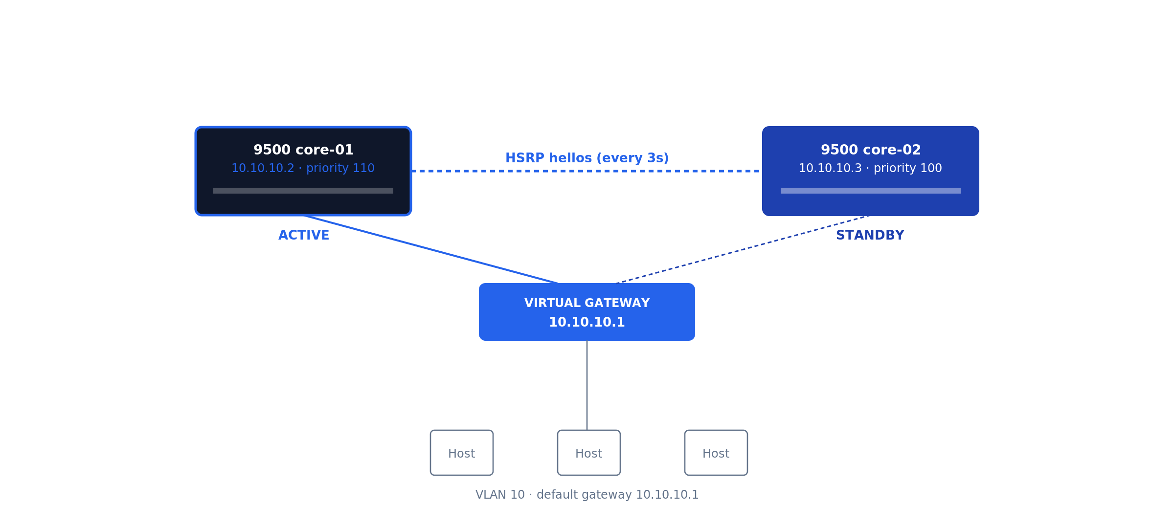
Hosts in VLAN 10 set their default gateway to 10.10.10.1 (the virtual IP). preempt ensures the higher-priority router takes ownership back when it returns.
Cisco-specific hardening & LACP uplinks
The Catalyst defaults are tuned for “deploy fast in a lab” — production needs more. Apply the Cisco IOS-XE Hardening Guide in full; this section is the highest-impact subset, mapped to NIST SP 800-53 Rev 5 control families AC-3, AC-17, AU-2, SC-7, SC-8.
Disable services running by default
dc1-distr-c9300-01(config)# no ip http server
dc1-distr-c9300-01(config)# no ip http secure-server
dc1-distr-c9300-01(config)# no service pad
dc1-distr-c9300-01(config)# no service finger
dc1-distr-c9300-01(config)# no service tcp-small-servers
dc1-distr-c9300-01(config)# no service udp-small-servers
LACP port-channel uplinks
Inter-switch uplinks should always use LACP for both throughput and resilience (Figure 06).
Figure 06 · LACP port-channel uplink
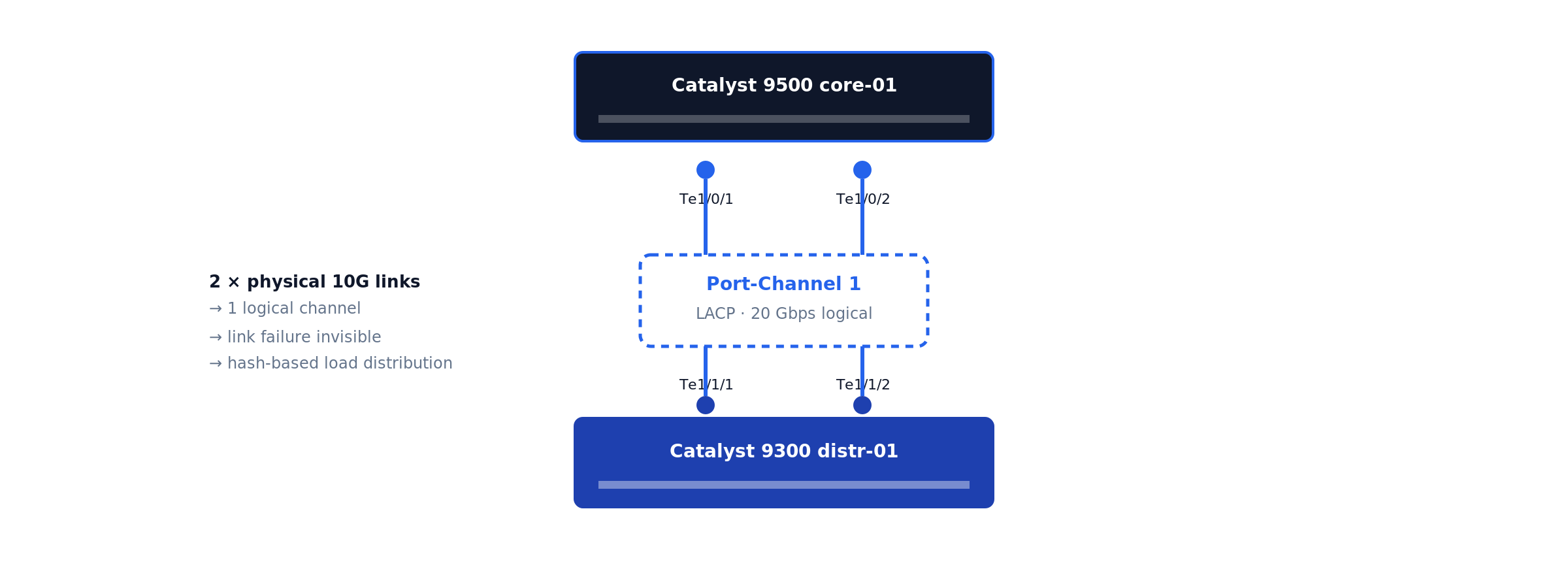
dc1-distr-c9300-01(config)# interface range TenGigabitEthernet1/1/1 - 2
dc1-distr-c9300-01(config-if-range)# channel-group 1 mode active
dc1-distr-c9300-01(config)# interface Port-channel1
dc1-distr-c9300-01(config-if)# switchport mode trunk
dc1-distr-c9300-01(config-if)# switchport trunk allowed vlan 10,20,99
DHCP snooping and Dynamic ARP Inspection
These prevent rogue DHCP servers and ARP-spoofing attacks. Trust only the uplinks. Figure 07 shows the DHCP relay packet flow.
Figure 07 · DHCP relay (ip helper-address) flow
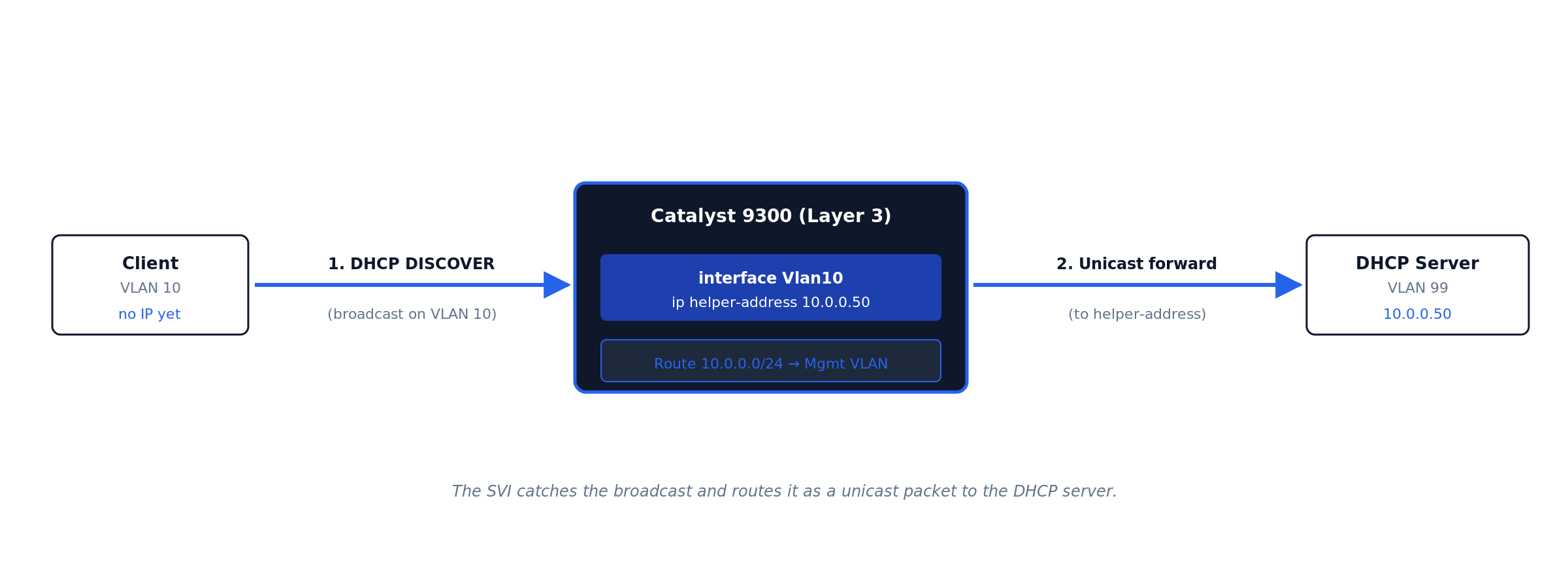
ip helper-address. The SVI catches the client’s broadcast DISCOVER, rewrites it as a unicast packet to the configured helper address, and routes it to the DHCP server in a different VLAN. · Click diagram to enlarge.dc1-distr-c9300-01(config)# ip dhcp snooping dc1-distr-c9300-01(config)# ip dhcp snooping vlan 10,20 dc1-distr-c9300-01(config)# ip arp inspection vlan 10,20 dc1-distr-c9300-01(config)# interface Port-channel1 dc1-distr-c9300-01(config-if)# ip dhcp snooping trust dc1-distr-c9300-01(config-if)# ip arp inspection trust
SNMPv3, TACACS+, remote syslog
Never SNMPv2c in production (cleartext community). Centralize auth via TACACS+ with local fallback. Ship logs to remote syslog from day one — the logs that matter during an incident are the ones from before the incident.
Stack configuration (Catalyst 9300)
The C9300 stacks up to 8 units via StackWise-480 (480 Gbps backplane). The newer C9300X family upgrades to StackWise-1T (1 Tbps). Either way, the stack appears as a single logical switch with a single management IP and config (Figure 08).
Figure 08 · StackWise ring topology
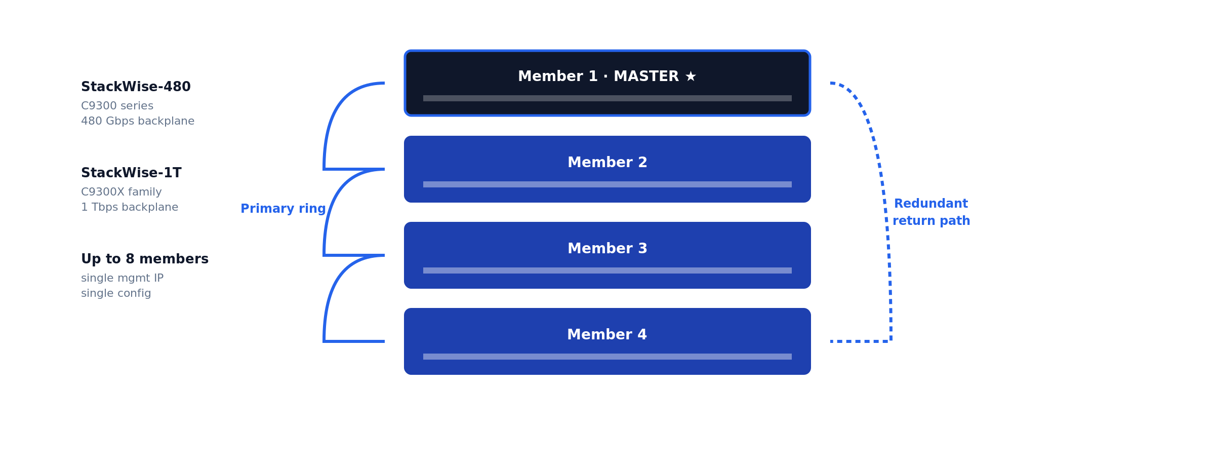
Do not mix IOS-XE versions across stack members. A stack with mismatched versions enters version-mismatch mode and one or more members drop offline until versions converge via auto-upgrade. Always pre-stage matching versions or schedule a maintenance window long enough to absorb the auto-upgrade reload.
How to verify Layer 3 routing is working
The Cisco-specific verification commands you actually need:
dc1-distr-c9300-01# show version
dc1-distr-c9300-01# show inventory
dc1-distr-c9300-01# show interfaces status
dc1-distr-c9300-01# show ip route
dc1-distr-c9300-01# show ip ospf neighbor
dc1-distr-c9300-01# show etherchannel summary
dc1-distr-c9300-01# show standby brief
dc1-distr-c9300-01# show ip dhcp snooping
dc1-distr-c9300-01# show license summary
dc1-distr-c9300-01# show switch
dc1-distr-c9300-01# write memory
The dump above is the full checklist. The six commands below are the ones that prove Layer 3 routing is actually working — what each validates, what healthy output looks like on the reference topology, and what to read from it.
show ip route — is the routing table built?
dc1-distr-c9300-01# show ip route
Gateway of last resort is 10.255.0.1 to network 0.0.0.0

S*    0.0.0.0/0 [1/0] via 10.255.0.1
      10.0.0.0/8 is variably subnetted, 8 subnets, 2 masks
C        10.10.10.0/24 is directly connected, Vlan10
L        10.10.10.1/32 is directly connected, Vlan10
C        10.10.20.0/24 is directly connected, Vlan20
L        10.10.20.1/32 is directly connected, Vlan20
C        10.10.30.0/24 is directly connected, Vlan30
L        10.10.30.1/32 is directly connected, Vlan30
C        10.255.0.0/30 is directly connected, TenGigabitEthernet1/1/1
L        10.255.0.2/32 is directly connected, TenGigabitEthernet1/1/1
Validates the heart of the system. Each healthy SVI produces a C (connected network) and L (local address) pair — a VLAN subnet missing here means its SVI is down, and no amount of host-side fiddling will fix that. Gateway of last resort must be set; if it reads not set, Internet-bound traffic dies at this switch. In an OSPF design you also expect O routes from neighbors — their absence means adjacencies are down.
show ip interface brief — are the L3 interfaces up?
dc1-distr-c9300-01# show ip interface brief | exclude unassigned
Interface              IP-Address      OK? Method Status                Protocol
Vlan10                 10.10.10.1      YES NVRAM  up                    up
Vlan20                 10.10.20.1      YES NVRAM  up                    up
Vlan30                 10.10.30.1      YES NVRAM  up                    up
GigabitEthernet0/0     10.99.99.10     YES NVRAM  up                    up
TenGigabitEthernet1/1/1 10.255.0.2     YES NVRAM  up                    up
The fastest triage view. up/up is the only acceptable state for a production SVI. administratively down means a missing no shutdown; down/down on an SVI means autostate has no live port in that VLAN — both are diagnosed in the troubleshooting section.
show vlan brief — do the VLANs exist and own the right ports?
dc1-distr-c9300-01# show vlan brief
VLAN Name                             Status    Ports
---- -------------------------------- --------- -------------------------------
1    default                          active    Gi1/0/45, Gi1/0/46
10   USERS                            active    Gi1/0/1, Gi1/0/2, Gi1/0/12
20   SERVERS                          active    Gi1/0/24, Gi1/0/25
30   VOICE                            active    Gi1/0/12
99   MGMT                             active
Validates that the L2 substrate under the SVIs is real. An SVI configured for a VLAN that does not appear here will never come up — creating the SVI does not create the VLAN. Confirm each access port shows up under the VLAN you intended; a user port stranded in VLAN 1 is invisible to every gateway you built.
show interfaces trunk — are the trunks carrying the right VLANs?
dc1-distr-c9300-01# show interfaces trunk
Port        Mode             Encapsulation  Status        Native vlan
Po1         on               802.1q         trunking      1

Port        Vlans allowed on trunk
Po1         10,20,30,99

Port        Vlans in spanning tree forwarding state and not pruned
Po1         10,20,30,99
Read all three stanzas, not just the first. A VLAN missing from allowed was pruned by switchport trunk allowed vlan on one side; a VLAN allowed but missing from the forwarding stanza is blocked by spanning tree or not active. Traffic for that VLAN silently dies on this link either way. Native VLAN must match both ends — a mismatch shows up here and as CDP error messages.
show arp — is the switch resolving hosts across VLANs?
dc1-distr-c9300-01# show arp | include Vlan
Internet  10.10.10.1             -   7035.0958.41c1  ARPA   Vlan10
Internet  10.10.10.50            4   a4bb.6dc2.118a  ARPA   Vlan10
Internet  10.10.20.1             -   7035.0958.41c2  ARPA   Vlan20
Internet  10.10.20.80           12   0050.56b3.9f04  ARPA   Vlan20
Validates the last hop. The dash-age entries are the SVIs themselves; the aged entries are live hosts the switch has resolved. If a host you are troubleshooting never appears here while you ping it from the switch, the problem is below Layer 3 — wrong access VLAN, cable, or host firewall — not routing.
show cdp neighbors — is the physical topology what the diagram says?
dc1-distr-c9300-01# show cdp neighbors
Device ID        Local Intrfce     Holdtme    Capability  Platform  Port ID
dc1-core-c9500-01.corp.example.com
                 Ten 1/1/1         154        R S I       C9500-24Y4C Ten 1/0/3
dc1-core-c9500-02.corp.example.com
                 Ten 1/1/2         141        R S I       C9500-24Y4C Ten 1/0/3
Validates cabling against intent before you trust any of the layers above it. Wrong Port ID against your documentation means the uplinks are swapped or the patch panel lies — find out now, not during the failover test. CDP is also the fastest detector of native VLAN mismatch: the switch logs %CDP-4-NATIVE_VLAN_MISMATCH within a minute of the misconfiguration.
Document everything in your IPAM/CMDB: device name, model, serial, IOS-XE version, Smart Licensing status, rack location, uplinks, purchase date, SMARTnet expiration. Set up automated config backups via Oxidized or RANCID from day one.
Troubleshooting inter-VLAN routing: nine failure modes
Ninety percent of “the Layer 3 switch is broken” tickets resolve to one of the nine patterns below. Work them in order — they are sequenced from the physical layer upward, the same layer-isolation discipline that applies to any network incident.
1. SVI stuck down/down
Symptoms: show ip interface brief shows the SVI down/down; hosts in the VLAN cannot ping their gateway.
Cause: Autostate. An SVI comes up only when its VLAN exists in the VLAN database and at least one physical port in that VLAN (access or trunk-allowed) is up and forwarding.
Resolution: Confirm the VLAN exists in show vlan brief; confirm a live port is assigned to it. On a bench switch with nothing connected, plug any port into the VLAN or test from a port-channel that allows it. Do not reach for the no autostate workaround in production — it masks real topology failures.
2. SVI administratively down
Symptoms: Status column reads administratively down.
Cause: The interface was never no shutdown-ed, or someone shut it during a change and the rollback missed it.
Resolution: interface Vlan20 → no shutdown. Then check the change log for why it was down — an SVI deliberately shut during an incident should not be silently revived.
3. IP routing not enabled
Symptoms: Every host pings its own gateway; nothing pings across VLANs. SVIs are all up/up. The switch itself can ping everything.
Cause: ip routing is missing — several Catalyst platforms ship with it disabled, and a write erase resets it. Without it the switch is a multi-gateway host, not a router.
Resolution: show running-config | include ip routing — if absent, configure ip routing in global config. Routing starts immediately; no reload.
4. Trunk not carrying the VLAN
Symptoms: Hosts on the local switch reach the gateway fine; hosts on a downstream access switch in the same VLAN cannot.
Cause: switchport trunk allowed vlan on one side omits the VLAN — classically, someone added VLAN 30 to the gateway switch and forgot the trunk statement, or used allowed vlan 30 (replace) instead of allowed vlan add 30 and wiped the list.
Resolution: show interfaces trunk on both ends; reconcile allowed lists. The add keyword is not optional knowledge — omitting it on a production trunk is a resume-generating event.
5. Native VLAN mismatch
Symptoms: Intermittent weirdness on a trunk: one VLAN leaks into another, STP errors, repeated %CDP-4-NATIVE_VLAN_MISMATCH log entries.
Cause: The untagged (native) VLAN differs across the two ends of an 802.1Q trunk, so untagged frames change VLANs in transit.
Resolution: Set it explicitly and identically on both ends — switchport trunk native vlan 99 — ideally to a dedicated unused VLAN, never VLAN 1 carrying user traffic.
6. Missing or wrong default route
Symptoms: All inter-VLAN traffic works; nothing reaches the Internet or remote sites. show ip route reads Gateway of last resort is not set.
Cause: The static default was never configured, points at the wrong next hop, or the OSPF default originate from the core stopped (check whether the core lost its upstream).
Resolution: Static design: ip route 0.0.0.0 0.0.0.0 <edge-router-ip> and confirm the edge router has return routes for your internal subnets — one-way reachability looks identical from the user side. OSPF design: chase the default back to whichever router should be originating it.
7. Host gateway misconfiguration
Symptoms: One host (or one DHCP scope worth of hosts) cannot leave its subnet; neighbors on the same VLAN are fine. The switch shows the host in show arp.
Cause: Host default gateway points at the wrong IP — stale static config, or a DHCP scope whose router option still hands out the old gateway after a migration. With HSRP, hosts configured with a physical SVI address instead of the virtual IP break on failover.
Resolution: Fix the DHCP scope option 3 (router) to the SVI — or HSRP virtual — address, and hunt down statically configured hosts. This is the failure mode that makes gateway migrations a change-control item, not a quick edit.
8. ACL silently dropping traffic
Symptoms: Some inter-VLAN flows work, others fail consistently by source, destination, or port. Pings may work while the application fails.
Cause: An ACL applied to an SVI (ip access-group ... in/out) is matching more than intended — usually an implicit deny doing exactly its job after someone appended a permit in the wrong order.
Resolution: show ip interface Vlan20 | include access list to find what is applied, then show access-lists and read the hit counters — the line with the climbing matches during a test is your culprit. Resequence rather than rewrite, and log-tag denies during the diagnostic window.
9. Duplicate IP address
Symptoms: Intermittent connectivity for one address that comes and goes with no config changes; %IP-4-DUPADDR in the log; ARP table flapping between two MAC addresses for the same IP.
Cause: A statically addressed device collides with the DHCP range, or worse, something is squatting on the SVI/HSRP address itself.
Resolution: show arp | include <ip> repeatedly to capture both MACs, trace each via show mac address-table address <mac> to a physical port, and remove the offender. Then fix the process gap: documented static ranges outside DHCP scopes — IPAM, not tribal memory.
Of the nine failure modes above, two dominate the after-hours calls we take: trunk allowed-lists that lost a VLAN during a change (mode 4 — almost always the missing add keyword), and DHCP scopes still handing out a decommissioned gateway after a migration (mode 7). Neither is visible from the switch that gets blamed. The estates that page us least have two things in common: explicit allowed-VLAN lists reviewed in change control, and automated config backups that make every change diffable the next morning.
Common day-one mistakes specific to Cisco IOS-XE
- Skipping Smart Licensing registration. Day 91 brings throttling. Configure CSSM transport on day 1.
- Leaving PnP enabled on a non-DNA shop. Every reboot hangs 10 min on PnP discovery.
- Forgetting
crypto key generate rsabefore SSH. No keys = silent SSH failures. - Mixing IOS-XE versions in a stack. Members go offline mid-day.
- TACACS without
localfallback. TACACS goes down → driving to the data center. - Forgetting
vrf-alsoon VTY access-class. Mgmt-vrf bypasses the ACL entirely. - Default-allowing all VLANs on trunk ports. Every broadcast crosses every link.
- Skipping
passive-interface defaulton OSPF. Hello packets leak to user SVIs. - No automated config backup. Switch dies, six hours rebuilding from memory.
Production design notes: spanning tree, redundancy, and monitoring
A Layer 3 boundary does not abolish Layer 2 — every VLAN below your SVIs is still a spanning-tree domain, and the interaction is where redundant designs quietly go wrong. Three rules from production:
Align STP root with the HSRP active router. Run spanning-tree mode rapid-pvst, hard-set root priority on the HSRP active switch (spanning-tree vlan 10,20,30 priority 4096, secondary 8192 on the standby). If root and active gateway diverge, inter-VLAN traffic takes an extra L2 hop across the inter-switch trunk for no reason — invisible until that trunk congests. Edge ports get portfast plus bpduguard; loops arrive via the cheap desktop switch someone smuggles under a desk, not via your engineered links.
Prefer routed redundancy to switched redundancy where you can. Distribution-to-core links built as routed point-to-points (the no switchport + /30 or /31 pattern) with OSPF + BFD converge in milliseconds and remove STP from the equation entirely; redundant L2 trunks with HSRP converge in seconds and keep STP in play. Where L2 adjacency must span switches — or the uplink needs raw capacity — bundle with LACP EtherChannel as covered in the hardening and LACP section: one logical link, no blocked redundant port, hitless single-member failure.
Instrument before the first incident. The remote syslog and SNMPv3 baseline from the hardening section is the floor. Add Flexible NetFlow on the Catalyst 9000 (flow monitor applied to the SVIs) so east-west traffic between VLANs is visible — when the server VLAN saturates, NetFlow tells you which conversation did it; interface counters only tell you that it happened. IP SLA probes between SVIs and toward the default gateway give you continuous data-plane truth that survives the “it was slow earlier” ticket. This telemetry layer is exactly what infrastructure performance monitoring consumes.
Layer 3 switch best practices
The configurations above keep a switch running; these conventions keep an estate maintainable for the five-to-ten years the hardware will actually serve:
- Make VLAN IDs encode the subnet. VLAN 10 ↔
10.x.10.0/24, VLAN 20 ↔10.x.20.0/24, consistently across every site. Every engineer who touches the network after you will either bless or curse this decision. - Name everything for the 2 a.m. engineer. Hostname encodes site/role/platform/unit (
dc1-distr-c9300-01); every interface gets adescriptionstating far end and circuit.show cdp neighborsshould confirm documentation, never substitute for it. - Document in systems, not spreadsheets. IPAM (NetBox or equivalent) is the source of truth for subnets, VLANs, and assignments; the CMDB carries serials, code versions, and support status — the same records that drive lifecycle planning decisions later.
- Summarize at boundaries. Each distribution pair advertises one summary upstream (
area rangein OSPF) instead of leaking every /24 into the core. Smaller tables, faster convergence, and a misbehaving access subnet cannot churn the campus. - Segment by policy, not convenience. Users, servers, voice, management, and IoT in separate VLANs with deliberate inter-VLAN ACLs at the SVI — the Layer 3 switch is your first east-west enforcement point, well before the firewall sees anything.
- Change-control the gateway layer. Every SVI, HSRP, trunk, and routing change rides a window with a written rollback — a gateway typo takes out a floor, not a desk. This is the discipline the change-control engagement above exists to enforce.
- Back up configurations automatically. Oxidized or RANCID from day one (see References), diff alerts on, restore actually tested. A dead switch with current backups is an RMA; without them it is a rebuild from memory at 2 a.m.
Lifecycle — SMARTnet and what comes after
A Catalyst 9300 goes through four commercial stages: Active production with SMARTnet → End of Sale (EoS) → End of Software Maintenance (EoSWM) → End of Support (EoSL).
The Catalyst 9300 first shipped in 2017. Models from the original launch are entering EoS / EoSWM in 2026-2028. Hardware itself is mechanically reliable for another 5-7 years past these dates — the constraint is vendor support, not hardware failure.
For organizations running Catalyst hardware past Cisco’s EoSL, post-SMARTnet Cisco maintenance provides TAC-equivalent engineering support, spare parts inventory, and SLA-backed response without forcing a hardware refresh. Cisco hardware lifecycle planning helps decide which switches to refresh, which to maintain, and which to consolidate. See also multi-vendor consolidation for organizations standardizing across Cisco, Juniper, HPE, and other platforms.
When to call WUC
This guide covers routine Catalyst 9000 deployment. Escalate to WUC if any of the following apply:
- The switch is going into a regulated environment (PCI-DSS, HIPAA, SOX, FedRAMP, CJIS) and the change is outside your existing change-control window.
- You’re refreshing from an older platform (3850 / 3650 / 4500-X) and need parallel-path migration with rollback windows defined for each phase.
- The deployment is part of a multi-site rollout where configuration consistency across 10+ switches matters.
- You inherited an existing Catalyst estate with no documentation and need a baseline audit of every switch.
- Your Catalyst hardware is past Cisco’s End-of-Software-Support and you need TAC-equivalent engineering coverage.
- You’re consolidating from multiple OEM contracts (Cisco + Juniper + HPE) into a single multi-vendor support engagement.
WUC engineers run multi-OEM enterprise infrastructure — Cisco Catalyst and Nexus, Juniper EX, HPE Aruba, plus the storage and server platforms most enterprise networks touch — under tiered SLAs with peer-reviewed change documentation. See Network Maintenance and Multi-Vendor Consolidation for engagement models.
Frequently asked questions
What is the difference between a Layer 3 switch and a router?
A Layer 3 switch routes IP traffic in forwarding ASICs at wire speed across high-density Ethernet ports, but offers little or no NAT, stateful inspection, or WAN connectivity. A router forwards in a more flexible (usually software-driven) path with full WAN, NAT, VPN, and large-table BGP support at far lower throughput per dollar. Inside the LAN, the switch wins; at the edge, the router does.
Can a Layer 3 switch replace a router?
For inter-VLAN routing and campus interior routing — yes, completely, and it will do the job faster. For Internet edge, WAN circuits, NAT, or site-to-site VPN termination — no. The standard enterprise pattern is Layer 3 switches for everything inside the building and a router or SD-WAN appliance facing the carrier.
How do I enable routing on a Cisco switch?
Three steps: enable the global routing process with ip routing (plus ipv6 unicast-routing if applicable), create an SVI per VLAN with interface Vlan10 and an IP address, and give the switch a way out — either a static default route or a routing protocol such as OSPF. Hosts then use each SVI address as their default gateway. The full procedure with verification is the body of this guide.
What is an SVI?
A switch virtual interface (SVI) is a logical Layer 3 interface bound to a VLAN. Its IP address acts as the default gateway for every host in that VLAN, and the switch routes between SVIs in hardware. One SVI per routed VLAN; an SVI only comes up when its VLAN exists and has at least one active port.
Do Layer 3 switches support dynamic routing protocols?
Yes. Catalyst 9000 switches run static routing, OSPF, EIGRP, IS-IS, and BGP; exact support depends on the license tier (Network Essentials vs Network Advantage). OSPF with BFD is the common campus choice. They are not designed to carry full Internet BGP tables — TCAM is sized for enterprise route counts, not the global table.
When should I use a router instead of a Layer 3 switch?
When the requirement involves WAN or Internet handoffs, NAT/PAT at scale, stateful or per-flow services, encrypted tunnels in volume, QoS shaping onto slow circuits, or full BGP tables. If the traffic leaves your building or needs per-session intelligence, route it through a router or firewall; if it stays on your Ethernet, keep it on the switch ASIC.
Final word: a Cisco Layer 3 switch setup that holds up
A production-grade Cisco Layer 3 switch setup is not the twenty minutes of SVI commands — it is the decisions around them: PnP disabled deliberately, Smart Licensing registered on day one, management isolated in its own VRF, inter-VLAN routing verified with the six commands above rather than assumed, gateways made redundant, and the whole thing documented and backed up before the first user ever touches it. Work the guide top to bottom and the switch you rack this week will still be boringly reliable when its refresh conversation comes up years from now. And when the deployment is bigger than one switch — or the change window carries compliance weight — that is what WUC network engineering is for.
References
- Cisco Systems. Recommended Releases for Catalyst 9200/9300/9400/9500/9600 Platforms. TAC suggested-release tracking.
- Cisco Systems. Smart Licensing Using Policy. Consolidated licensing guide, Cisco Catalyst 9000 Series switches.
- Cisco Systems. Cisco IOS XE Software Hardening Guide. Device-hardening reference.
- Baker, F. RFC 1812 — Requirements for IP Version 4 Routers. IETF.
- Nadas, S. RFC 5798 — Virtual Router Redundancy Protocol (VRRP) Version 3. IETF.
- NIST. SP 800-53 Rev. 5 — Security and Privacy Controls for Information Systems and Organizations.
- Oxidized project. Oxidized — network device configuration backup. GitHub.
Find our field guides faster in Google. Add WUC Technologies as a preferred source and our engineering guides carry a “preferred” badge in your Search results, AI Overviews, and AI Mode.